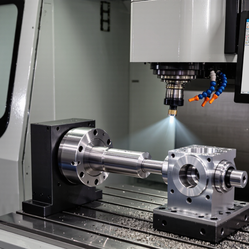
| 1 | Design and CAD Modeling | A three-dimensional part model is created with the required dimensions, holes, radii, threads, surface requirements, and material information. | Units: millimeters or inches
Geometry: solid model, holes, pockets, slots, and contours
Drawing information: dimensions, datums, and tolerances | CAD software and engineering drawings | A digital definition of the metal component |
| 2 | CAM Programming | The CAD model is converted into toolpaths that define how the cutting tool will remove material from the workpiece. | Toolpath types: facing, roughing, finishing, drilling, and threading
Cutting data: spindle speed, feed rate, depth of cut, and step-over
Output: machine-readable G-code or equivalent numerical-control code | CAM software and post-processor | A verified machining program |
| 3 | Material Selection and Preparation | A metal blank is selected according to strength, corrosion resistance, thermal performance, machinability, and final application requirements. | Common metals: aluminum, steel, stainless steel, brass, copper, and titanium
Stock forms: bar, plate, block, tube, or casting
Allowance: extra material is retained for machining | Material saw, stock preparation tools, and measuring equipment | A correctly sized and identified workpiece |
| 4 | Workholding and Machine Setup | The workpiece is secured, tools are loaded, and the machine establishes the relationship between the part, cutting tools, and coordinate system. | Setup data: work offset, tool length offset, fixture location, and tool number
Important condition: the part must be held rigidly without excessive distortion | CNC mill, CNC lathe, vise, chuck, fixture, probes, and tool holders | A repeatable machining setup |
| 5 | Machine Calibration and Program Verification | The operator checks tool offsets, coordinate directions, program travel, clearance, and possible collisions before cutting the metal. | Checks: dry run, single-block operation, toolpath simulation, and offset verification
Safety factors: adequate clearance and correct spindle direction | Control panel, simulation software, probes, and inspection tools | A validated program and safer first operation |
| 6 | Roughing | Larger cutting tools remove most of the unwanted material efficiently, leaving a controlled amount for later finishing operations. | Objective: high material-removal rate
Typical strategy: multiple passes with a programmed stock allowance
Key controls: cutting load, chip evacuation, coolant, and tool deflection | Carbide end mills, drills, turning tools, and coolant system | A near-net-shape component with machining allowance |
| 7 | Finishing | Smaller or specialized tools perform the final passes to achieve the specified dimensions, geometry, edge condition, and surface finish. | Operations: finish milling, reaming, boring, threading, chamfering, and turning
Surface finish: commonly specified using Ra values
Dimensional control: depends on machine condition, tool wear, material, and setup | Finish mills, reamers, boring tools, taps, thread mills, and turning tools | A finished part close to its design requirements |
| 8 | In-Process Inspection | Critical features are measured during production so that offsets can be corrected before a dimensional problem affects additional parts. | Measured features: diameter, length, position, flatness, perpendicularity, and surface condition
Typical tools: calipers for general checks and micrometers or gauges for closer control | Calipers, micrometers, height gauges, probes, and bore gauges | Early detection of dimensional variation |
| 9 | Deburring and Cleaning | Sharp edges, burrs, chips, and cutting fluid are removed without changing the functional geometry of the component. | Methods: hand deburring, abrasive tools, brushing, washing, or controlled tumbling
Requirement: preserve critical edges, holes, threads, and mating surfaces | Deburring tools, brushes, washers, and compressed-air systems | A clean and safe-to-handle part |
| 10 | Final Inspection | The completed part is compared with the engineering drawing or digital inspection plan before release. | Inspection data: dimensional results, geometric tolerances, surface finish, material traceability, and visual condition
Typical capability: standard CNC work may achieve approximately ±0.1 mm; tighter values require controlled equipment, tooling, and process conditions | Coordinate-measuring machine, optical comparator, gauges, and surface tester | Documented conformity decision |
| 11 | Optional Post-Processing | Additional treatments may be applied to improve corrosion resistance, hardness, wear resistance, appearance, or dimensional stability. | Examples: anodizing for aluminum, plating, passivation for stainless steel, heat treatment, powder coating, and surface polishing
Note: treatment can affect dimensions and should be included in the design plan | Specialized finishing and heat-treatment equipment | Improved functional or cosmetic performance |
| 12 | CNC Process Output | CNC machining produces accurate, repeatable metal parts by controlling tool movement along programmed axes while material is removed. | Common machine types: 3-axis, 4-axis, and 5-axis machining centers; CNC lathes for rotational parts
Main variables: axis motion, spindle speed, feed rate, tool geometry, workholding, coolant, and inspection control | CNC machining center or CNC turning center | A repeatable metal component manufactured from digital instructions |