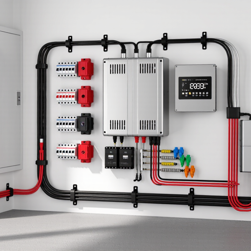
| Primary purpose | Organizes, routes, and terminates the direct-current wiring between a wall-mounted battery system and connected equipment. | It combines electrical conductors, connectors, protective components, and mounting features into an organized interface. |
| Nominal system voltage | 48 V DC nominal; the actual battery voltage varies according to cell chemistry, state of charge, and charging conditions. | The harness must be selected for the battery’s maximum operating voltage, not only its nominal label. |
| Main power conductors | A positive conductor and a negative conductor, commonly made from flexible, fine-stranded copper cable. | The conductors carry charging and discharge current between the battery terminals, protection device, and load or charger. |
| Conductor sizing | Determined by continuous current, peak current, cable length, allowable voltage drop, installation temperature, and insulation rating. | Larger or shorter conductors generally reduce voltage drop and heat generation, but the final size must follow the applicable electrical design rules. |
| Overcurrent protection | A fuse or DC-rated circuit breaker is normally installed close to the battery’s positive terminal. | It helps protect the cable and connected equipment from excessive current caused by short circuits or overloads. |
| Isolation and service disconnect | A manually operated DC disconnect may be included in the harness or installed adjacent to the battery. | It allows technicians to isolate the battery from the system during installation, inspection, or maintenance. |
| Battery-management connections | Low-voltage signal wiring may connect the battery-management system to sensors, displays, chargers, inverters, or other battery units. | These circuits can carry monitoring and control signals, but they do not replace the main power cables. |
| Connector requirements | Connectors must be rated for the system’s DC voltage, maximum current, conductor size, temperature range, and environmental conditions. | Correctly rated connectors help maintain low contact resistance and reduce the risk of overheating or accidental disconnection. |
| Mounting interface | May include a bracket, cable-entry plate, strain-relief points, terminal cover, and defined attachment points on the wall or battery enclosure. | The interface supports the battery and keeps wiring aligned, protected, and accessible for service. |
| Cable routing | Cables are routed with suitable bend radii and secured so that they do not hang from terminals or rub against sharp edges. | Proper routing limits mechanical stress, insulation damage, electromagnetic interference, and accidental short circuits. |
| Polarity identification | Positive and negative conductors should be clearly color-coded, labeled, or otherwise identified at both ends. | Clear identification reduces the risk of reverse-polarity connection and simplifies testing and maintenance. |
| Grounding and bonding | Metallic mounting parts and enclosures may require protective bonding or grounding according to the installation design and local electrical requirements. | Bonding can provide a fault-current path and help keep exposed conductive parts at a safer potential. |
| Environmental protection | The required enclosure and connector protection depends on indoor or outdoor location, moisture, dust, corrosion, and temperature exposure. | Sealing, suitable insulation, and corrosion-resistant hardware help preserve electrical and mechanical performance. |
| Thermal considerations | Cable ampacity and connector temperature rise must be evaluated under the expected load and ambient conditions. | Loose terminals, undersized conductors, and restricted airflow can create localized heating. |
| Installation sequence | Mount the support, route and secure the harness, install protection and disconnect devices, verify polarity, then complete electrical connections with the battery isolated. | A controlled sequence reduces accidental energization, wiring errors, and mechanical damage. |
| Inspection checks | Verify polarity, terminal torque, cable support, insulation condition, fuse or breaker rating, connector engagement, and clearance from heat or sharp edges. | These checks help confirm that the wall-mounted battery interface is electrically sound and mechanically secure before energization. |